September 14, 2026
Point Cloud to BIM Services: From 3D Laser Scanning to Revit
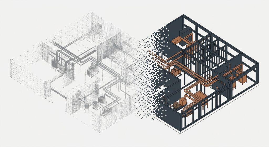
A point cloud to BIM service takes scan data someone else already captured and turns it into a coordinated Revit model. That distinction matters, because a lot of firms search for “scan to BIM” when what they actually have is a finished point cloud sitting on a drive and a modeling gap they need filled, not a scanning gap.
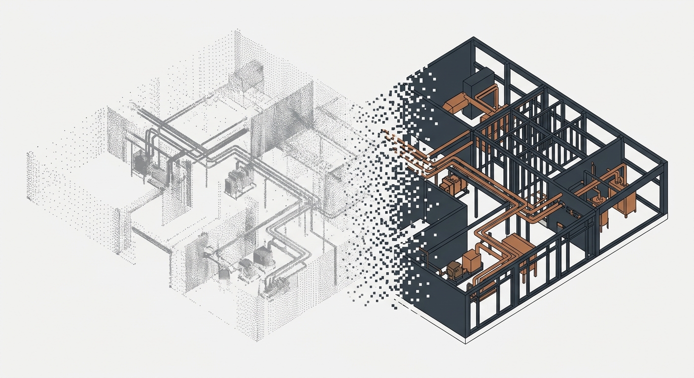
Surveying firms run into this constantly. So do contractors who commissioned a scan for one purpose and later need it modeled for another. If you already have the cloud, you do not need a company that also owns scanners. You need a modeling team that can pick up where the scan left off.
What the Service Actually Covers
Point cloud to BIM modeling means building a native Revit file from scan data across whichever disciplines the project calls for: architectural and structural elements first (walls, floors, roof framing), then mechanical, electrical, and any process piping, each modeled as its own linked file. The last step pulls every discipline into one coordinated container and checks the geometry against the source cloud.
What you do not get from a modeling-only service is the scan itself. If you need both capture and modeling, that is two services, even when one provider offers both under one roof.
What You Send: Formats That Actually Work
Revit reads point clouds natively in two formats: RCP and RCS, Autodesk’s own container and scan formats. Everything else, including the open, vendor-neutral E57 standard, has to run through Autodesk ReCap for indexing before Revit can link it. Send whichever format your scan came in. A modeling team that has done this before will index it themselves rather than bouncing the file back to you.
The Modeling Process, Discipline by Discipline
Here is where the actual work happens, and where the differences between providers show up.
Architecture and structure come first. Floor slabs, walls, columns, and roof framing get modeled directly against the cloud, because everything else in the building references these elements for position.
Mechanical, electrical, and process piping follow. Pumps, ducts, conduit runs, cable trays, and piping each get modeled as real Revit families with actual connection points, not generic boxes standing in for equipment. The level of detail here depends on what the model needs to do afterward: coordination-only work needs accurate connection points and routing; fabrication or procurement work needs dimensionally accurate, connected systems.
Coordination happens last. Every discipline gets linked into one federated file, georeferenced to the project’s coordinate system, and checked for clashes between systems: a duct crossing a structural beam, a pipe run with no clearance for a support hanger.
Software gets you through the mechanical parts of this. It does not tell you whether a wall reads out of plumb because it was built that way or because the scan picked up noise at that surface. That call, made correctly and consistently across a few thousand elements, is most of what separates a usable model from one that is technically accurate and practically useless.
Where the Modeling Hours Actually Go
An open floor plan with a handful of walls models fast. A mechanical room with dense piping, supports, and multiple systems crossing the same ceiling space takes meaningfully longer per square foot, because the hours scale with how much has to be interpreted and connected, not how much square footage the room covers. A quote that does not ask about MEP density before pricing the job is usually guessing.
QA: Checking the Model Against the Source
A finished model gets checked against the point cloud it came from, not just reviewed for whether it looks right in a 3D view. That means confirming geometry accuracy against the cloud, running a clash check between disciplines, and cleaning out unused families and views before delivery. Skipping this step is how a model ends up looking complete while quietly drifting from what is actually built.
What You Receive
A typical deliverable includes the native Revit file (.rvt), export formats like .ifc and .dwg for teams not running Revit, and often 2D sheets, plans, sections, elevations, generated directly from the coordinated model. Some projects also want a QA report showing the model was validated against the source scan rather than handed over on faith.
When This Is the Right Service to Look For
If you are a surveying firm that already owns the scan and the client relationship, a point cloud to BIM partner fills the Revit gap without you building a modeling team for volume that may not be steady. If you are a contractor or facility team with an old scan and a new use case, the same logic applies: the capture already happened, and what is left is turning it into something Revit can use.
If you are still deciding between a flat CAD deliverable and a full parametric model, that is a separate question worth answering first, since it changes what the modeling scope needs to include.
Have a Point Cloud Ready to Model?
If you already have scan data and need it turned into a coordinated Revit model, tell us about the project and we will scope it against the disciplines and LOD it actually needs.